


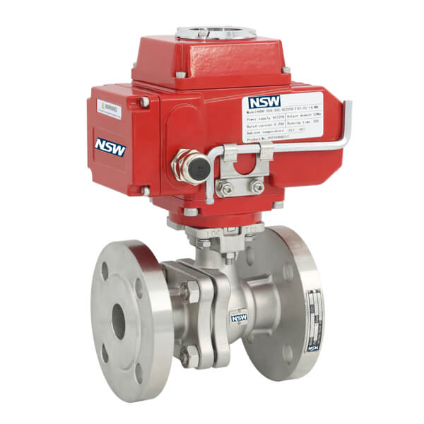
What is a Motorized Ball Valve
Motorized Ball Valve also called Electric Actuator ball valves, It It belongs to the category of motorized valve and automatic control valve, This combines motorized actuators with quarter-turn valves to enable remote fluid control. These automated valves execute precise open/close operations or flow modulation through electrical signals in industrial control systems.
Core Components Breakdown
1. Electric Actuator Assembly
- Receives 4-20mA/0-10V control signals
- Converts electrical energy to mechanical torque (50-2000Nm)
- Features gear reduction systems (≤3.5s response time)
2. Ball Valve Mechanism
- Valve body: Stainless steel/CF8M construction
- Rotating ball: 90° rotation with full/partial bore
- Seat design: PTFE/metal-to-metal sealing
How Does a Motorized Ball Valve Work
The working principle of the Motorized Ball Valve is to receive the control signal through the electric actuator, drive the motor to rotate, and then use the transmission mechanism (such as gears, worm gears) to make the ball rotate around the valve stem axis, so as to realize the opening and closing or adjustment function of the valve. Specifically, when the electric actuator receives the control signal from the control system, it will drive the motor to rotate, and the motor will then transmit the torque to the ball through the transmission mechanism, so that it rotates around the valve stem axis. When the ball rotates 90 degrees, the channel opening of the valve changes, so as to realize the connection, disconnection or adjustment of the medium.
How Motorized Valve Actuators Work
Core Functions in Automation
Industrial electric actuators serve as control system enablers by:
- Translating PLC/DCS commands to valve movements
- Maintaining process parameters (flow/pressure/temperature)
- Providing position feedback via 4-20mA transmitters
Technical Specifications
| Type | Torque Range | Applications |
| Quarter-Turn | 50-2000Nm | Ball Valves, Butterfly Valves, Plug Valves |
| Multi-Turn | 5-25kN Thrust | Gate Valves, Globe valves |
Operation Mechanism of Motorized Ball Valves
1. Signal Reception: Controller sends command to actuator
2. Torque Conversion: Gearbox reduces motor RPM
3. Flow Control:
– Full open: Ball channel aligns with pipeline
– 90° closed: Ball blocks fluid path
– Modulating: V-port design enables 10-90% flow
Key Advantages & Technical Features
- Automation Ready: Seamless integration with SCADA/DCS
- Zero Leakage: Dual seal design (ANSI/FCI 70-2 compliant)
- High CV Values: Full-bore design minimizes ΔP
- Corrosion Resistance: 316SS/Alloy C276 options
- Longevity: 100,000+ cycle durability
Industrial Applications
Critical Use Cases
1. Process Industries:
– Chemical dosing systems
- Petrochemical pipeline isolation
– Pharma CIP/SIP processes
2. Infrastructure:
– HVAC chilled water control
– Wastewater treatment plants
– Natural gas distribution
3. Energy Systems:
– Steam line isolation
– Cogeneration plant controls
– Compressed air systems
Selection Criteria & Classification
Configuration Options
- Connection Types:
– Flanged (ANSI 150#-900#)
– Threaded (NPT/BSPP)
– Wafer-style
- Flow Control:
– 2-Way/3-Way configurations
– V-port precision control
– Full vs reduced bore
Pro Tip: For high-cycle applications, specify actuators with <10% duty cycle rating and IP67 protection.
Post time: Apr-13-2025